Real3D
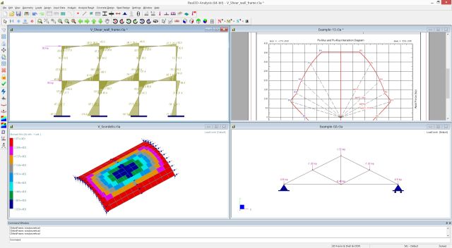
Real3D is a powerful structural design / finite element analysis software designed for structural engineers of all skill levels. The software is reliable, easy to use, and affordable. It is designed for accuracy and simplicity in mind, allowing engineers to get the job done without being overwhelmed by useless features. It features unique quad-precision solver, which is able to handle numerically challenging structures. It incorporates a blazingly fast sparse solver based on Intel Math Kernel Library and is able to solve models with millions of degrees of freedom. Other key features include spreadsheet input and output, easy to use command line input, as well as compelling graphics display built upon industry standard OpenGL(R).
Since its inception in 2002, Real3D has been licensed and sub-licensed to hundreds engineering offices in the United States and around the world. We offer various license options, including complete source code licensing. We understand you have many choices in selecting your structural software, so ask yourself this question: "Why would I pay more for something that is less accurate and more difficult to use?"
Click here for some example videos.
Here is an article published in the Dec, 2022 issue of the Structure Magazine:Reducing FEM Solution Errors with Quad Precision Arithmetic with Real3D.
Elements
- 2D and 3D frame (beam and truss) elements, with linear, tension-only or compression-only options
- 2D and 3D four-node plate/shell element, with thick or thin plate bending element (for slab modeling) and compatible/incompatible in-plane stress element (for shear wall modeling)
- 3D eight-node solid (brick) element with compatible and incompatible formulations
- linear and nonlinear nodal, line and surface springs.
- Coupled springs (advanced)
- Moment releases on frame element
- Rigid offset and rigid links
- Element stiffness modifications
- Forced displacements on supports
- Rigid diaphragms in any orientations
- Multi-DOF constraints including inclined rollers, equal constraints etc.
- Nodal, point forces and moments, line and surface forces, self-weight, area loads, thermal loads, pattern loads, and moving loads
Analysis and Design Options
- Static linear analysis.
- Geometric nonlinear (P-Delta) analysis.
- Frequency analysis.
- Response spectrum analysis.
- Sparse solver (in-core and out-of-core) for static and frequency analyses, able to solve very large models with millions of degrees of freedom.
- Standard double-precision skyline solver and unique quad-precision skyline floating point solver (extremely accurate for "numerically challenging" models).
- Concrete design for beams, columns, and slabs according to ACI 318-2019, -2014, -2011, -2008, 2005, and -2002. It includes such as features as exact biaxial column interaction diagrams, automatic moment magnification, cracked section properties, Wood-Armer moments, color coded plots for member capacity, and reinforcement contour plots for plates.
- Steel design according to AISC 360-22 (16th edition) LRFD, AISC 360-16 (15th edition) LRFD, and AISC 360-10 (14th edition) LRFD. It features step-by-step calculation procedures in Word and PDF formats for each design choice.
User Interface Features
- Multiple documents may be opened at the same time; each document may have multiple views with different display settings.
- Spreadsheets for input data and results.
- Graphically drawing nodes, frames and finite elements via mouse click or keyboard in command window.
- Quality 3D graphical rendering built on OpenGL(R) with hidden line or surface removal. Graphics display includes loading diagram, moment and shear diagrams for beams, contours for shells and solids, deflection diagram and annotations for input and results.
- Powerful automatic model generations for continuous beams, 2D and 3D frames, 2D and 3D shells, arc beams, and non-prismatic beams. Include AISC steel shape database, ASTM rebar database, regular sections and standard load combinations.
- Flexible editing features such as undo/redo, duplicate, array, move, scale, delete, revolve, extrude, splitting beams, sub-mesh shells, and node and element merging.
- Automatic mesh generator to produce 100% quadrilateral shells.
- Many different selection methods such as window/point select, select by IDs, select by properties, with options to freeze or thaw parts of a model. Ability to pan, zoom, and rotate in real time.
- Ability to append one or more input files.
- Report in plain text, HTML, Word, and PDF formats. Graphic report may contain multiple images.
- Ability to activate/inactivate elements and include/exclude gravity at element level.
- Print previews for graphics and text reports.
- Ability to import from and export to DXF files.
- Ability to import / export AISC steel shapes from/to a comma delimited (csv) file.
- English or Metric units, or combination of the two.
- True 64-bit, fully integrated Windows application, professionally written from the ground up in standardized, object-oriented C++ programming language, resulting in a truly robust software tool for the structural engineering community.
System Requirements
Operating System: x64 Windows 7, 8, 10, 11. ARM64 Windows 11

What our clients are saying:
I like this program because of its ease of use, the computation speed. Of all of the programs like this that I have used I find that this software permits the most cost effective use of my time. I highly recommend its use in offices of any size.
-N. B. Mitchell, Jr. P.E. S.E.
Real3D is a lot faster than many famous structural software (like 13 seconds for Real3D vs. 1+ minutes for others for the same tank structure).
-Mr. B. Evangelista